Serial I2C LCD Daughter Board Module
The Serial I2C LCD converter for the popular display with controller for example, 2×16 characters. Thanks to this system, two data lines and supply 5 Volts and groundare enough to connect the screen.
Converter I2C for display with the controller so that the screen requires only two lines – SDA and SCL. Via the bus, from the level of the Arduino, can be controlled the displayed text and the backlight, including turning them off or on at any time. On board is also a potentiometer to adjust the contrast.

In order to use a library for the Arduino, the system should be soldered in accordance with the picture above.
Fearures:
- Converter of I2C bus
- Installed resistors pulling up the lines of the I2C bus – 4.7 k Ω
- Converter based on PCF8574
- Soldered potentiometer to adjust the contrast
- The ability to control the backlight through the I2C bus
- The possibility of changing the bus address via soldering jumpers A0, A1, A2
Addressing I2C
Depending on what chipset, this module can have different address spaces:
- Chipset PCF8574 – 0x20
- Chipset PCF8574T – 0x27
- Chipset PCF8574A – 0x38
- Chipset PCF8574AT – 0x3F
To be sure, we recommend the use of a program for Arduino I2C Scanner that reads the I2C addresses for all connected devices.
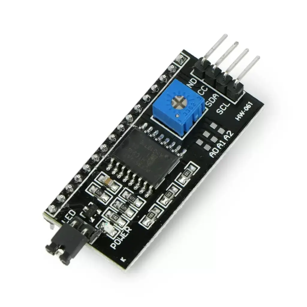
PINOUT:
The system has four leads and a jumper which putting out causes turning off the backlight of the screen. On the board is also goldpin strip which is fixed to the populardisplays based on driver. All leads are soldered.

| No. | Name | Description |
| 1 | GND | Mass. |
| 2 | VCC | Power +5 V. |
| 3 | SDA | The data line of the I2C bus. |
| 4 | SCL | Clock line of the I2C bus. |
Connecting of the display
On the back of the tile is 16-pin, male strap goldpin to solder the display based on the controller.
Useful links
Alternative Products
These other products might interest you